Star News


")


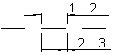
The length of the dotted line in the drawing. Drawing lines

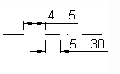
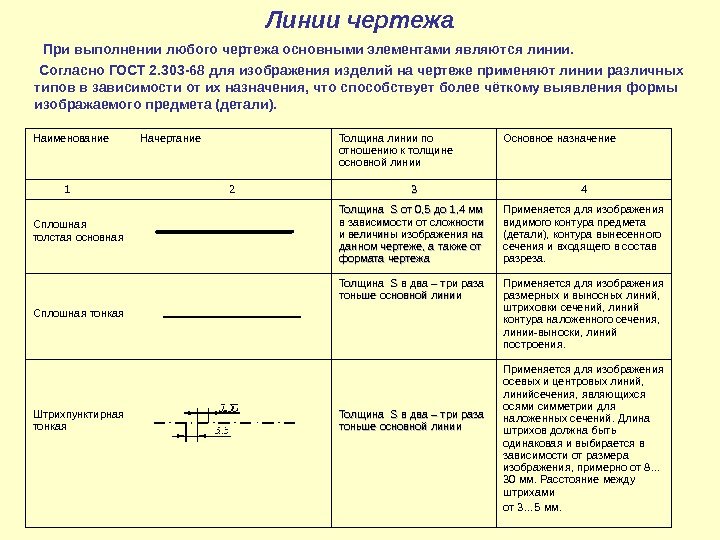 Drawing lines In any drawing, the main elements are lines. According to GOST 2. 303 -68, lines of various types are used to depict products in a drawing, depending on their purpose, which contributes to a clearer identification of the shape of the depicted object (detail). Name Style Line thickness in relation to the main line thickness Main purpose 1 2 33 4 Solid thick main line Thickness S S from 0.5 to 1.4 mm depending on the complexity and size of the image in this drawing, as well as on the format of the drawing Used to image the visible the contour of the object (detail), the contour of the rendered section and the contour that is part of the section. Solid thin Thickness SS is two to three times thinner than the main line. It is used to display dimension and extension lines, hatching of sections, contour lines of the superimposed section, leader line, construction lines. Dash-dot thin Thickness SS is two to three times thinner than the main line Used to display axial and center lines, section lines, which are the axes of symmetry for superimposed sections. The length of the strokes should be the same and is selected depending on the size of the image, from about 8 ... 30 mm. The distance between the strokes is from 3 ... 5 mm.
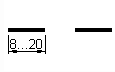
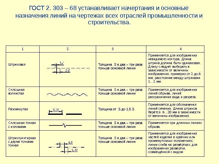 GOST 2. 303 - 68 establishes the styles and main purposes of lines in the drawings of all industries and construction. 1 2 3 4 Stroke Weight SS two to three times thinner than the main line Used to draw an invisible outline. The stroke length must be the same. The length should be chosen depending on the size of the image, approximately from 2 to 8 mm, the distance between the strokes is 1 ... 2 mm. Solid Wavy Thickness SS is two to three times thinner than the main line Used to depict break lines, view and section demarcation lines. Open Thickness SS to 1.5 SS Used to mark section lines. The length of the strokes is taken 8 ... 20 mm, depending on the size of the image. Solid thin with breaks The thickness of SS is two to three times thinner than the main line Used for long break lines. Dash-dotted with two dots thin Thickness SS is two to three times thinner than the main line Used to depict parts of the product in extreme or intermediate positions; fold lines on reamers; for a sweep image combined with a view
![]()
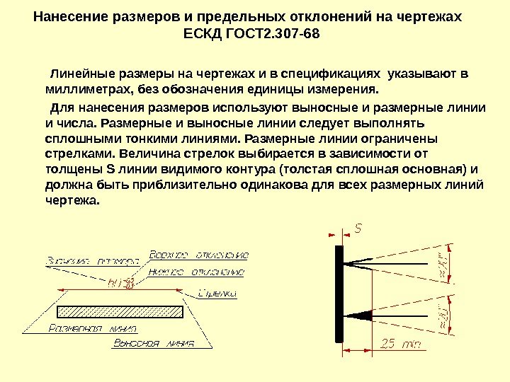 Application of dimensions and maximum deviations on the drawings of ESKD GOST 2. 307 -68 Linear dimensions on the drawings and in the specifications are indicated in millimeters, without indicating the unit of measurement. For dimensioning, extension and dimension lines and numbers are used. Dimension and extension lines should be made with solid thin lines. Dimension lines are limited by arrows. The size of the arrows is selected depending on the thickness S of the line of the visible contour (thick solid main) and should be approximately the same for all dimension lines of the drawing.
 Setting the dimensions of the circles that determine the relative position from a common base Setting the dimensions of several groups of elements from several common bases
 Setting dimensions between adjacent elements (chain) When drawing the dimension of a straight segment, the dimension line is drawn parallel to this segment, and the extension lines are perpendicular to the dimensions the lines should rest with their tip against the corresponding contour lines, or extension, or center lines.
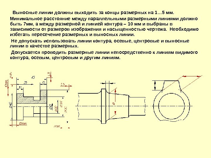 The extension lines should extend beyond the ends of the dimensional lines by 1 ... 5 mm. The minimum distance between parallel dimension lines should be 7 mm, and between the dimension line and the contour line - 10 mm and are selected depending on the size of the image and the saturation of the drawing. Avoid crossing dimension and extension lines. Do not allow the use of contour lines, axial, center and extension lines as dimension lines. It is allowed to draw dimension lines directly to the lines of the visible contour, axial, center and other lines.
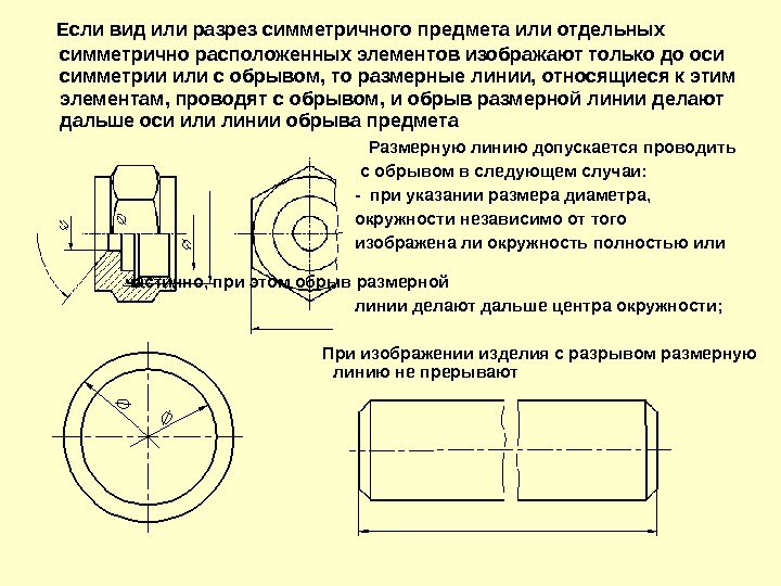 If a view or section of a symmetrical object or individual symmetrically located elements is depicted only up to the axis of symmetry or with a break, then the dimension lines related to these elements are drawn with a break, and the break of the dimension line is made further than the axis or break line of the object. The dimension line can be drawn with a break. in the following cases: - when specifying the size of the diameter, the circle, regardless of whether the circle is shown in full or in part, while the break of the dimension line is done further than the center of the circle; When depicting a product with a break, the dimension line is not interrupted
 If the length of the dimension line is not sufficient to place arrows on it, then the dimension line continues to be extended beyond the extension lines (or contour, axial, center, etc.) Examples of applying dimension numbers Applying dimensions of radii
 With a large radius, it is allowed to bring the center closer to the arc, in this case I show the dimension line of the radius with a break at an angle of 90 ° Drawing the radius of the arc with approximation Drawing the radius of the arc, when it is not required to specify the dimensions to the center of it, which determine the position of its center Drawing several radii from one center.
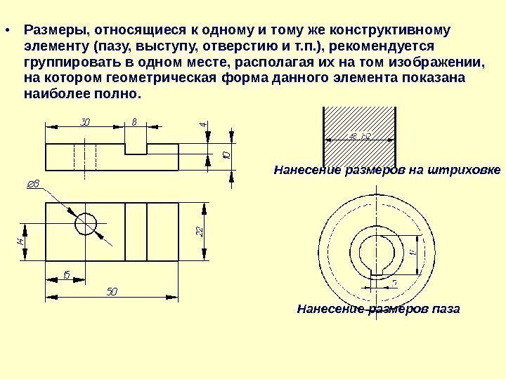 Dimensions related to the same structural element (groove, protrusion, hole, etc.) are recommended to be grouped in one place, placing them on the image in which the geometric shape of this element is shown most fully. Dimensioning a hatch Dimensioning a slot
 The dimensions of several identical elements of the product, as a rule, are applied once, indicating the number of these elements on the shelf of the leader line. When applying the dimensions of elements evenly spaced around the circumference (for example, holes), instead of angular dimensions that determine the relative position of the elements, only their number is indicated.
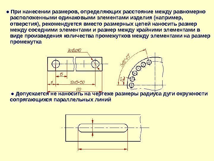 ● When applying dimensions that determine the distance between evenly spaced identical elements of the product (for example, holes), it is recommended that instead of dimensional chains, apply the dimension between adjacent elements and the dimension between the extreme elements as the product of the number of gaps between elements and the gap size ● It is allowed not to apply dimensions on the drawing the radius of the circular arc of mating parallel lines
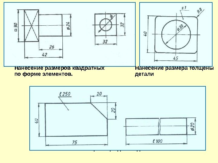 Applying square dimensions Applying dimensions are thick according to the shape of the elements. Details Dimensioning the Length of a Part
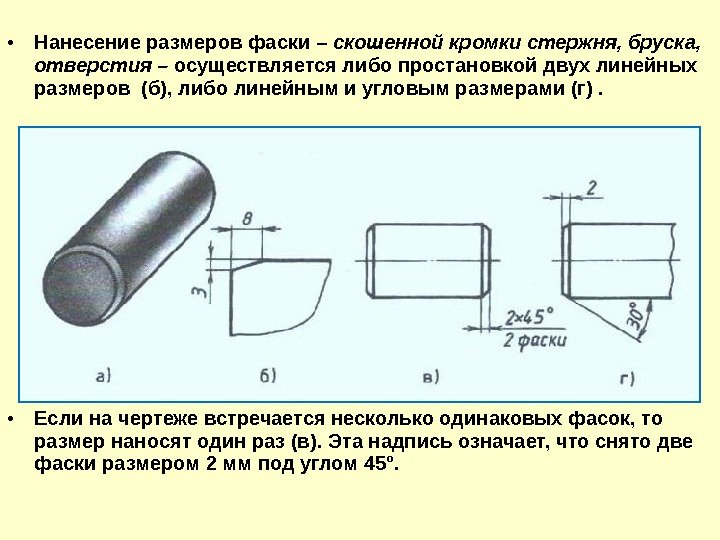 The application of the dimensions of the chamfer - the beveled edge of the rod, bar, hole - is carried out either by setting two linear dimensions (b), or by linear and angular dimensions (d). If there are several identical chamfers in the drawing, then the size is applied once (c). This inscription means that two chamfers of 2 mm in size were removed at an angle of 45 °.
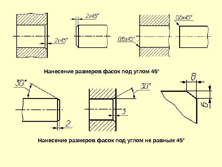 Dimensioning chamfers at an angle of 45° Dimensioning chamfers at an angle other than 45°
 Overall dimensions are the dimensions that determine the limiting values of the external outlines of the product. The overall dimensions include the dimensions of the length, width, height of the product. Examples of applying overall dimensions
Date: 2010-09-07
Lines in engineering drawing, their style, thickness and purpose are regulated by GOST 2.303-68. It describes nine types of lines, but we will consider 6 of them, the most common in educational drawings. This is how they look:
1. Solid thick main line From the name it is clear that this line is the main one. Intended: image of lines of a visible contour, contour lines of sections (both taken out and included in the section), the inner frame of the drawing, etc. The thickness of this line should be within 0.5 ... 1.4 mm, depending on the size and complexity of the drawing, as well as on its format. The thickness of the solid main line is taken as S, and in the future this value is used to obtain the thicknesses of all other lines.
2. solid thin line Its thickness should be S / 3 ... S / 2. Assigned to display contour lines of the superimposed section, dimension and extension lines, hatch lines, callouts.
3. dashed line Thickness S/3 ... S/2. Purpose: the image of lines of an invisible contour.
4. Dash-dotted thin line Thickness S/3 ... S/2. Used to depict axial and center lines, section lines, which are the axes of symmetry for superimposed or extended sections.
5. Solid wavy line Thickness S/3 ... S/2. Purpose: the image of break lines, lines of demarcation of the view and section.
6. open line Thickness S ... 1.5s. This line is used when depicting the positions of cutting planes of simple and complex cuts and sections. Don't think it's such a thick dotted line. No. She is depicted in the drawing - only two pieces. In this case, the main image, the section of which is actually determined by this line, is located between them.
Important additions The thickness of lines of the same type must be the same for all images in this drawing, drawn at the same scale. Please note that the thickness of the main solid line in the drawing must be the same both when depicting views and when drawing the sheet frame and the title block of the drawing (do not forget that not only the main lines are used in the title block of the drawing).
And finally. If you want to get acquainted with GOST 2.303-68 in more detail, then you can free download GOST from this link: download
Practical use
Let's try to understand the practical application, how to use lines in a drawing. You can see an example of using line types below:
or write down our phone number and tell your friends about us - someone is probably looking for a way to make drawings
or create a note about our lessons on your page or blog - and someone else will be able to master the drawing.
GOST 2.303-68
INTERSTATE STANDARD
ONE SYSTEM
DESIGN DOCUMENTATION
LINES
(approved by the Committee of Standards, Measures and Measuring Instruments under the Council of Ministers of the USSR in December 1967)
Instead of GOST 3456-59
1. This standard establishes the styles and main purposes of lines in the drawings of all industries and construction.
Special purpose of lines (image of threads, slots, boundaries of zones with different roughness, etc.) are defined in the relevant standards of the Unified Design Documentation System.
The standard complies with ST SEV 1178-78, ST SEV 6306-88.
(Changed edition, Rev. N 1, 2).
2. The name, style, thickness of the lines in relation to the thickness of the main line and the main purpose of the lines must correspond to those indicated in Table 1. Examples of the use of lines are shown in Figures 1-9.
3. For complex cuts and sections, it is allowed to connect the ends of an open line with a dash-dotted thin line.
Rice. 1. Connecting complex cuts and sections with a dash-dotted thin line
4. In construction drawings in sections, visible contour lines that do not fall into the sectional plane are allowed to be made with a solid thin line (Fig. 9).
5. Thickness of the solid main line s should be in the range from 0.5 to 1.4 mm, depending on the size and complexity of the image, as well as on the format of the drawing.
The thickness of lines of the same type must be the same for all images in this drawing, drawn at the same scale.
Table 1. “Name, style and thickness of lines”
| solid thick | S(0.5 to 1.4mm) | Lines of visible contour Transition lines visible Contour lines of the section (exposed and included in the section) |
|
|---|---|---|---|
| Solid thin | From S/3 to S/2 | Superimposed Contour Lines Dimension and extension lines Hatching lines Leader lines Leader line shelves and label underlining Lines for depicting border details ("furnishings") Callout Limit Lines in Views, Sections, and Sections Transition lines are imaginary Traces of planes, lines for constructing characteristic points for special constructions |
|
| Solid wavy | - | Cliff lines View and section lines |
|
| dashed | - | Hidden contour lines Transition lines invisible |
|
| Dash-dot thin | From S/3 to S/2 | Lines axial and center Section lines, which are the axes of symmetry for superimposed or extended sections |
|
| Dash-dot thickened | From S/3 to 2 S/3 | Lines indicating surfaces to be heat treated or coated Lines for depicting elements located in front of the cutting plane (“superimposed projection”) |
|
| open circuit | From S up to 1½ S | Section lines | |
| Solid thin with kinks | From S/3 to S/2 | Long break lines | |
| Dash-dotted two-dot thin | From S/3 to S/2 | Fold lines on reamers Lines for depicting parts of products in extreme or intermediate positions Lines for the image of the development, combined with the view |
Drawing 1. "Example of applying lines"
Drawing 2. "Example of applying lines"
Drawing 4. "Example of applying lines"
Drawing 5. "Example of applying lines"
Drawing 6. "Example of applying lines"
Drawing 7. "Example of applying lines"
Drawing 8. "Example of applying lines"
Drawing 9. "Example of applying lines"
Note. The position numbers in Fig. 1-9 correspond to the numbers of the items in Table 1.
(Changed edition, Rev. N 1).
6. The smallest thickness of lines and the smallest distance between lines, depending on the format of the drawing, must correspond to those indicated in Table 2.
7. The length of strokes in dashed and dash-dotted lines should be chosen depending on the size of the image.
8. The strokes in the line should be approximately the same length.
9. The spaces between the strokes in the line should be approximately the same length.
10. Dash-dotted lines must intersect and end with dashes.
11. Dash-dotted lines used as center lines should be replaced by solid thin lines if the diameter of the circle or the dimensions of other geometric shapes less than 12 mm in the image (Fig. 10).
Drawing 10. "Dash-dotted lines used as center lines"
Location of views in the drawing
In engineering drawing, the image of the visible part of the surface of an object facing the observer is called view.
The names of the species depend on which side the object is viewed from when projecting (Fig. 1.7).
Rice. 1.7.
A - direction of gaze b - location
The starting point in the drawing is front view, which is also called main view.
If you look at the object on the left, at right angles to the profile plane of the projections, you get left view.
When looking at an object from above, perpendicular to the horizontal projection plane, one gets view from above.
The directions in which they look at the part, receiving one or another view, are indicated in Fig. 1.7, A arrows with captions.
Each view occupies strictly certain place in relation to the main view. The left view is placed to the right of the main view and on the same level with it, the top view is placed under the main view (Fig. 1.7, b). You cannot violate this rule by placing views in arbitrary places without a special designation (without explanatory inscriptions).
Knowing the rule for the arrangement of views, it is possible to represent the shape of an object from its flat images. To do this, you need to compare all the views given in the drawing, and recreate in the imagination the three-dimensional shape of the object.
The understanding of the drawing is facilitated by comparing the shape of the part or its individual parts with geometric bodies. About a nut blank, for example, we can say that it has the shape of a hexagonal prism with a cylindrical hole (Fig. 1.8, A), and about the bolt blank - that its shape is composed of a cylindrical rod and a head in the form of a hexagonal prism (Fig. 1.8, b).
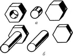
Rice. 1.8.
lines
To make the drawing more expressive and understandable for reading, it is performed in different lines, the outline and purpose of which are established by GOST 2.303–68 for all industries and construction.
Some of them depict real-life surfaces - visible and invisible contours. Other lines show where the planes of symmetry of the object, etc., pass; these are conditional and auxiliary lines that do not show the real outlines of the object. It is clear that these lines should be different in outline from the lines depicting the existing contours of the part.
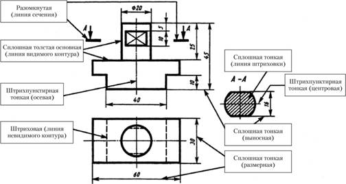
On fig. 1.9 used the main lines established by GOST 2.303–68 used in the execution of drawings.
Solid thick main line. To depict the visible contours of objects, a line is used, which is called a solid thick main line. The thickness of this line, denoted by the Latin letter s, is set by the standard in the range from 0.5 to 1.4 mm, depending on the size and complexity of the image, as well as on the format of the drawing. The selected line thickness s must be the same for all images in this drawing, made at the same scale.
Such a line circles the image of the visible outlines of the object in Fig. 1.9.
dashed line. For invisible outlines of an object, a line is used, which is called a dashed line. On fig. 1.9, such a line shows the outlines of the object invisible in the top view: the surfaces of the right and left cutouts and two flats.
Rice. 1.9.
The dashed line consists of strokes (dashes) of approximately the same length. Their length is set by the standard in the range from 2 to 8 mm (4 mm is recommended for training drawings). The distance between the strokes is taken from 1 to 2 mm, but approximately the same for a given line. The line thickness depends on the selected thickness of the solid main line and is taken from s/2 to s/3. This means that the thickness of the dashed line is 2–3 times thinner than the main one.
It is incorrect to call a dashed line dashed. A dot in German is "point", hence the name - dotted.
Many years ago, the dotted line performed the functions that another line, the dashed line, has now begun to perform. A dotted line is a line consisting of dots and having a different purpose.
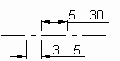
Dash-dotted swampy line. To draw axial, as well as center lines indicating the centers of circles, use a line called a dash-dotted thin line, which consists of strokes and dots between them. The length of the strokes is selected in the range from 5 to 30 mm, the distance between them is from 3 to 5 mm (for educational drawings, the length of the strokes is recommended to be 20 mm). The length of the strokes in the line should be approximately the same, the same applies to the distance between the strokes. The thickness of the dash-dotted line is from s/3 to s/2.
Axial and center lines should protrude beyond the contour of the image by 2-5 mm and end with a dash, not a dot. The position of the center of the circle is determined by the intersection of the dashes of the dash-dotted line, as shown in Fig. 1.9. If the diameter of the circle in the drawing is less than 12 mm, then the dash-dotted lines used as center lines are replaced by solid ones (without breaking them).
Drawing details should begin with drawing very thin solid lines in place of future axial and center lines (of course, if there are any). With their help, it is convenient to build symmetrical images, setting aside the dimensions from them, according to which the outlines of the object are drawn.
Dash-dotted thin line with two dots. To draw a fold line on the scans, a thin line with a dash-dotted line with two points is used. The length of the strokes is selected from 5 to 30 mm, and the distance between the strokes is from 4 to 6 mm. The thickness of this line is the same as that of the dash-dotted thin line, i.e. from 5/3 to 5/2.
Solid thin line. In addition to the lines listed in Fig. 1.9 marked with inscriptions dimension and extension lines.
Extension lines are used to connect the image and dimension lines drawn outside the outline. For dimensional and remote lines, a line is used, called a solid thin line, the thickness of which is from 5/3 to 5/2.
The extension lines should extend beyond the ends of the dimension line arrows by approximately 1–5 mm.
solid thin lines also used for hatching in sections.
Thus, the thickness of dashed, dash-dotted thin and solid thin lines is 2–3 times thinner than the main line.
As you can see, the names of the lines characterize them. The dashed one consists of strokes, the dash-dotted one consists of strokes and dots, the solid thin one is thinner than the solid main one.
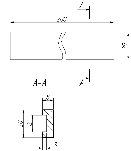
Open line. An open line is used to show where the section lines go (see Figure 1.9). Its thickness is chosen from s up to 1.55, and the length of the strokes - from 8 to 20 mm. For training drawings, the thickness of the strokes is usually taken 1.5 times thicker than the solid main line, and the length of the strokes is 12 mm. The strokes of the open line must not cross the outline of the image. On fig. 1.9 an open line shows where the section line passes A-A. Arrows showing the direction of view are applied at a distance of 2-3 mm from the outer ends of the open line.
The thickness of lines of the same type should be the same for all images in this drawing, drawn at the same scale. In this case, the thickness of the lines depends on the selected thickness s of the solid main line.
Subjects, depending on the size, complexity and purpose of the drawing, can be drawn in full size or on a certain scale.
The scale is the ratio of the linear dimensions of the object depicted in the drawing to the linear dimensions of the object itself in kind.
The image scales used for all industries and construction are divided into three groups: natural size, reduction scales and enlargement scales.
The scales of images in the drawings should be selected from the following range:
– life size – 1:1;
– reduction scales – 1:2; 1:2.5; 1:4; 1:5; 1:10; 1:15; 1:20; 1:25; 1:40; 1:50; 1:75; 1:100; 1:200; 1:400; 1:500; 1:800; 1:1000;
– magnification scales – 2:1; 2.5:1; 4:1; 5:1; 10:1; 20:1; 50:1; 100:1.
It is preferable to carry out the image of the object in full size, since the drawing is completely similar to the depicted object in shape and size.
Regardless of the scale of the image, only the actual dimensions of the object are always put on the drawing.
The scale designation is entered in column 6 of the main inscription by type: 1:1; 2:1; 1:2 etc.
If any image in the drawing is made on a scale that differs from that indicated in the main inscription, then the value of the scale is put in brackets near this image. For example, an additional view along the arrow A made in 5:1 scale. Above this image is the following entry: A(5:1).
Scales are not used when making clichés, photocopies, photographs, diagrams, etc.
7. Lines (gost 2.303-68)
The standard establishes the name, drawing rules and main purposes of lines in the drawings of all industries and construction (see Table 2).
table 2
Drawing lines
|
2. Solid |
From to |
Contour lines of the superimposed section. Dimensional and extension lines. Hatching lines. Callout lines. Lead line shelves. Lines for images of border details ("furnishings"). Lines of limiting external elements in views, sections and sections. Transition lines are imaginary. Traces of planes, lines for constructing characteristic points for special constructions |
|
|
3. Solid wavy |
From to |
Cliff lines View and section lines |
|
|
4.Dashed |
|
From to |
Lines of an invisible contour. Transition lines invisible |
|
5.Dash-punk dash thin |
|
From to |
Lines axial and center. Section lines, which are the axes of symmetry for superimposed or extended sections |
|
dotted thickened |
From to |
Lines indicating surfaces to be heat treated or coated. Line for displaying elements located in front of the cutting plane ("superimposed projection") |
|
|
before |
Section lines |
|
|
8. Solid thin with kinks |
From to |
Long break lines |
|
|
9. Dash-dotted with two dots |
|
From to |
Fold lines on reamers. Lines for the image of the sweep, combined with the view. Lines for depicting parts of products in extreme or intermediate positions |
Thickness S a solid main line is taken in the range from 0.5 to 1.4 mm, depending on the size and complexity of the image, as well as on the format of the drawing.
An example of the application of some lines is shown in fig. 7.1.
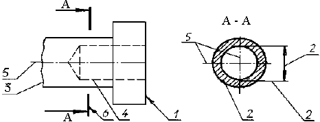
Rice. 7.1. An example of the use of lines: 1 - solid basic thick (lines of a visible contour); 2 - solid thin (hatching lines, remote, dimensional); 3 - solid wavy (cliff line); 4 - dashed (lines of an invisible contour); 5 – dash-dotted thin line (axial and center lines); 6 - open (section line)
The thickness of the lines of the same purpose should be the same on the same drawing (sheet) for all images drawn at the same scale.
Some guidelines for tracing drawings:
1. The length of strokes in dashed and dash-dotted lines should be chosen depending on the size of the image. Recommended sizes for dashed lines: stroke length 4–6 mm, distance between strokes 1–2 mm; for dash-dotted lines: stroke length 15–20 mm, distance between strokes 3–4 mm.
2. The strokes in the line must be the same length.
3. The spaces between the strokes in each line must be the same.
4 Dash-dot lines must intersect and end with dashes.
5. If the size of a circle or other geometric shapes is less than 12 mm, then the dash-dotted lines used as axial and center lines are replaced by solid thin lines.
6. Axial and center lines should be removed from the contour of the image of the object by 3–5 mm.
7. The contours of the parts at the points of contact of the lines should be depicted as a solid main line, without thickening.
Thin lines are outlined first, then thick ones.